SAFIERY UNIVERSITY
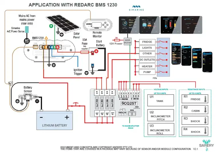
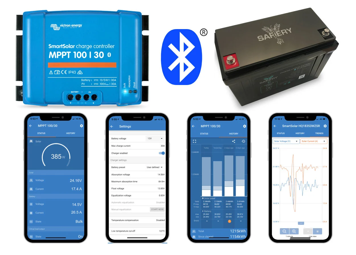
TREND FEATURE VICTRON BLUETOOTH MESH NETWORK SMART SOLAR + SAFIERY LITHIUM
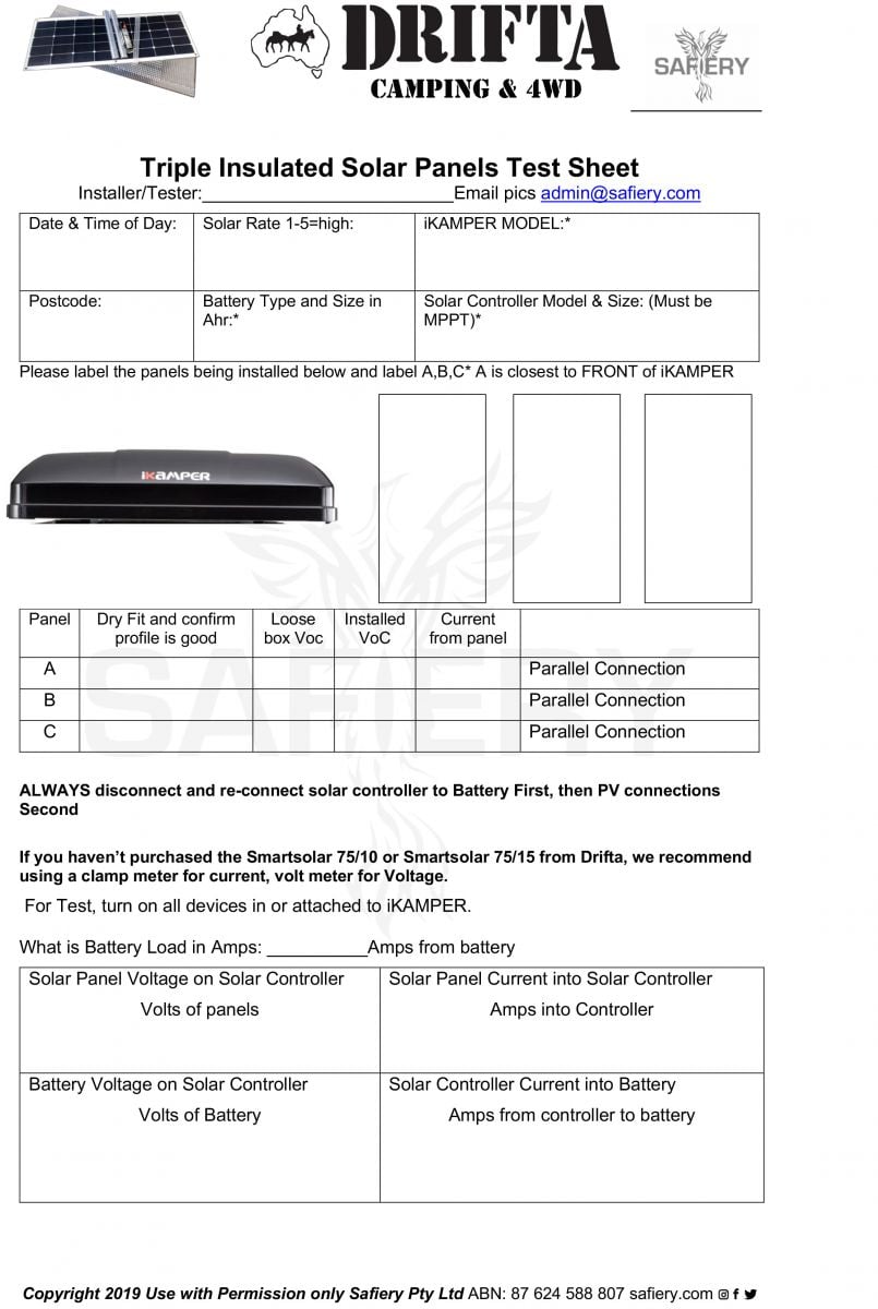
This technical article outlines the new Trend Feature on the Victron Connect App with their Smart Solar controller in a bluetooth mesh array with a Safiery Lithium battery.

Bluetooth Mesh Connection Battery and Solar has new Trend Feature
1. SMART SOLAR IS READING BATTERY VOLTAGE VIA BLUETOOTH
Highest efficiency giving maximum solar performance:
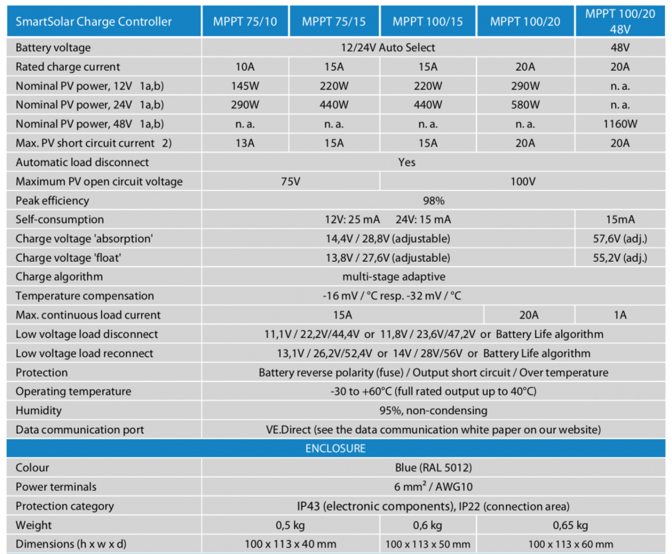
- No cooling fan. Maximum efficiency exceeds 98%.
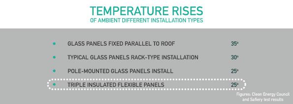
- Full output current up to 40°C Flexible charge algorithm
2. ULTRAFAST MPPT SOLAR CONTROLLER by VICTRON
- Especially in case of a clouded sky, when light intensity is changing continuously, an ultra-fast MPPT controller will improve energy harvest by up to 30% compared to PWM charge controllers and by up to 10% compared to slower MPPT controllers.
3. ADVANCED MAXIMUM POWER POINT DETECTION.
- If partial shading occurs, two or more maximum power points may be present on the power-voltage curve. Conventional MPPTs tend to lock to a local MPP, which may not be the optimum MPP. The innovative Victron Solar algorithm will always maximize energy harvest by locking to the optimum MPP.
4. FULLY PROGRAMMABLE CHARGE PARAMETERS.
- Most MPPT solar controllers have pre-set values for Lithium batteries. Redarc and others use 14.5V for bulk charging. This means the last 5% or so of charging Lithium will be less efficient and slower than this controller. By setting the bulk charge voltage higher at say 14.6V, the Lithium batteries will be charged to 100% quickly.
5. LITHIUM BATTERY VOLTAGE IS TRANSMITTED OVER BLUETOOTH NETWORK.
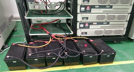
- Most solar controllers read the battery voltage at the terminals of the solar charge controller. In many cases this voltage has slight losses. It may be because the solar controller is not close to the battery or natural voltage loss in the cable. As a result, charging efficiency is lost. However, on the Safiery network, the actual Lithium battery voltage is transmitted to the Solar control via the bluetooth network. The accuracy is 0.01V. It does not matter how far away the solar controller is, though having cabling of significant size is important for efficiency.
6. COMPENSATES ABSORBTION AND FLOAT VOLTAGE WITH BATTERY TEMPERATURE.
- Most solar controllers don’t read battery temprature. However, on the Safiery network, the actual Lithium battery temperature is transmitted to the Solar control via the bluetooth network. The accuracy is 0.1C. It does not matter how far away the solar controller
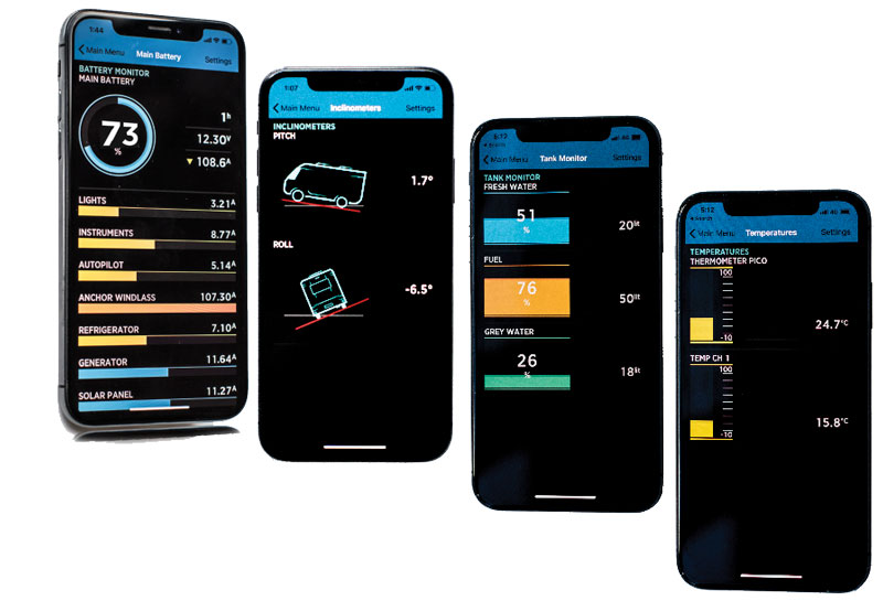
7. REAL TIME TREND FEATURE (NEW)
-
- Up to 7 variables can be trended in REAL TIME on the Victron Connect app updating every second. Great for tuning the orientation of your solar panels and for trouble shooting when performance has slowed from multiple panel arrays.
- Panel Voltage
- Panel Current
- Panel Watts
- Battery Voltage
- Battery Current
- Battery temperature (if battery transmitting via Bluetooth mesh battery voltage and temperature)
- Load Current (if load connected directly to solar controller)
8. HISTORY display options
- Solar history for today, yesterday, last week and up to 30days is visible on your Smartphone. It connects using Bluetooth into the mesh network.
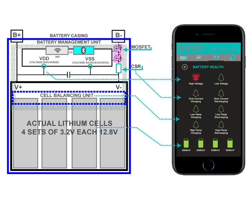
BLUETOOTH NETWORK CONNECTED LITHIUM BATTERIES MAXIMIZE EFFICIENCY
Lithium 100% Charging Efficiency
- Most Lithium batteries have 100% charging efficiency. This means if you charge with 100Ah of solar, it will absorb and is capable of discharging the same amout.
Bluetooth Network Connected
- Most bluetooth Lithium batteries have a single bluetooth interface to a smartphone app. That gives you information on your phone but you dont want to be the optimizer of your solar system. Safiery Bluetooth Lithium batteries can connect to the solar controller directly and of course your smartphone. Let the direct bluetooth connection do the heavy lifting of optimization while you sit back and enjoy liesure time.
Advanced Charge Acceptance rate
- The speed that a Lithium Battery will soak up the solar charging is dependent on the charge accetance rate of the Lithium battery. The charge acceptance rate is a function of the internal battery resistance: i.e. how well the cells are connected in the battery lowers the resistance and less energy is wasted internally. Safiery Lithium batteries have one of the lowest internal resistance specifications and it is the most crucial factor in our specification with suppliers and quality testing.

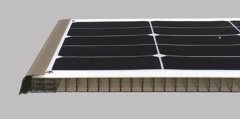


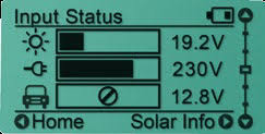 Monochrome LED Display
 Gorilla Glass, Retina quality