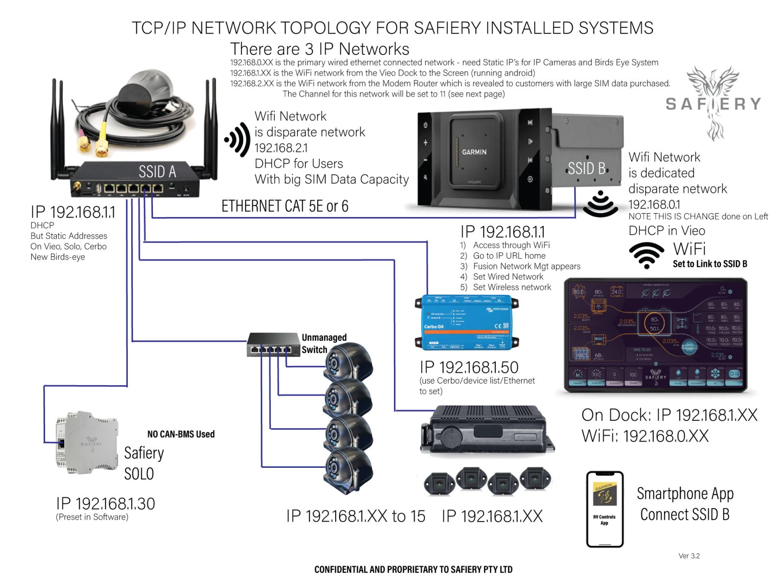
ETHERNET WIRED CONNECTION
The topology is shown in the picture below. It is required to be installed in this way so that:
- IP Cameras to operate hardwired to this network, then WiFi to the tablet if in the vehicle.
- Birdseye Camera (effectively an IP Camera) to operate hardwired to this network, then WiFi to the tablet if in the vehicle.
- Victron Remote Console App to operate hardwired to this network
- Other apps installed on the Vieo operate over this network via the installed modem
- Online and Over The Air (OTA) updates of Vieo and installed Apps
- The Subnet selection MUST be exactly as labelled.
To set the Vieo IP address:
- Connect eithernet from laptop to Vieo
- Perform IP scan
- Open IP address of the Vieo device
- Fusion Network Manager appears
- Go to the Wired tab and set the IP address as 192.168.1.80
- Go to the Wireless tab and check that the DHCP is selected and it is the 192.168.0.1
- Power Cycle the Vieo
Update the firware of the Vieo
- Ensure the modem is online
- Go to settings > Updates
- Select updates and download. This may take 15-20 mins for BOTH maps and operating firmware
- After the update, power cycle the vieo (Best Practice is to always power cycle any device after firmware update)
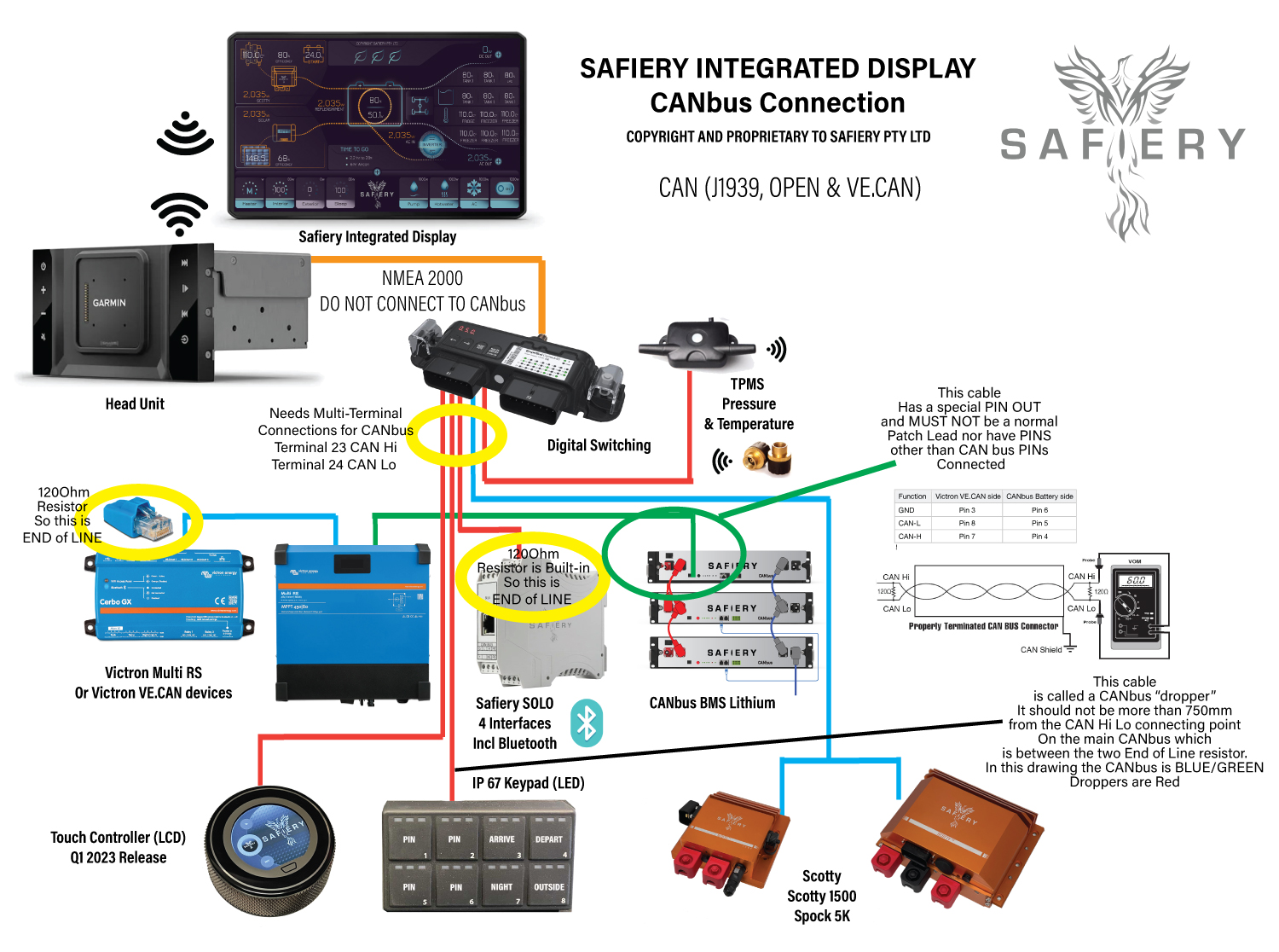
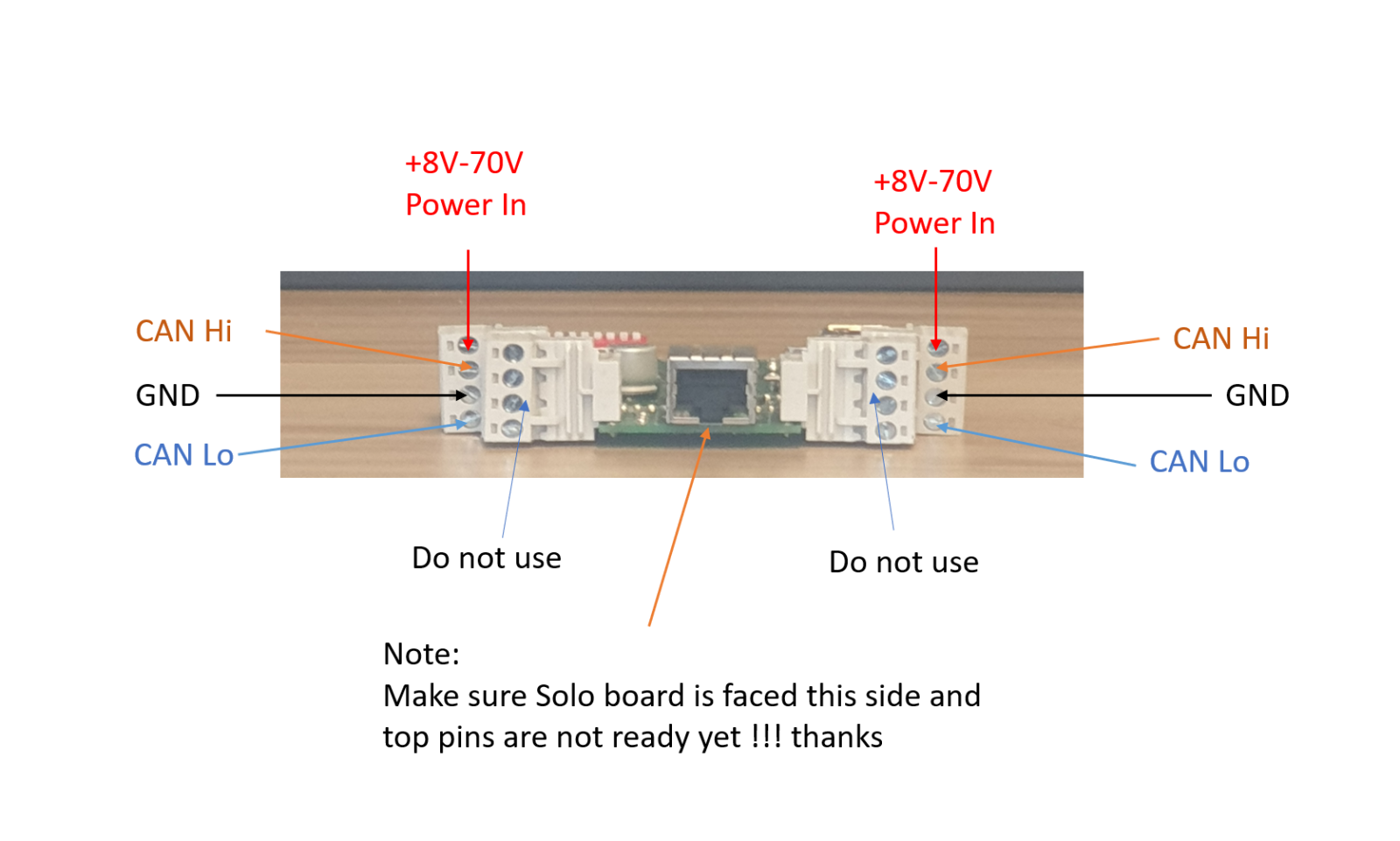
CANbus WIRED CONNECTION
The topology is shown in the picture below.
The CAN-bus is galvanic isolated.
- Ch 23 = CAN Hi and Ch 24 = CAN Low.
- LED indication 23 will indicate when transmitting message “Tx”
- LED indication 24 will indicate when receiving message “Rx” to Connect-50.
- Install the shield with only one end (suggest close to the Connect 50 grounded
Safiery’s CAN operates at 250 baud. (This is between low-speed and high-speed CAN.)
Two external 120-ohm terminal resistor must be installed in each end of the CAN-bus. Because some devices have built-in EOL and others done, we suggest this topology. It can be changed but the resistance measured at the end of installation (unpowered network) to ensure compliance.
- Scotty has a 120 Ohm resistor built in and so at one end of the line.
- Connect 50 does not have EOL built in.
- TPMS does not have EOL built in.
- Victron VE.CAN devices (Cerbo, Multi RS, Smart Solar CAN) do not have EOL built in
- Solo does not have EOL built in. Place it at the other end of line and add 120 Ohm precision resistor
Measure the resistance of the CAN (and 485) Network
Measure with a multi-meter the resistance between CAN-High and CAN-Low. Make sure the power supply is completely turned off. You should measure 60 Ohms over these 2 wires, because there are two 120 Ohms resistors in parallel. (If there are 3 resistors in the wiring, you will measure 40 Ohms, and with 4 resistors you will measure 30 Ohms.)
An Alternative is a short dropper STAR Connection
After some testing on a short dropper (less than 3m), you can make a star configuration, effectively a zero length bus with up to 8 unterminated stubs and a single central termination resistor of 120 ohms. The CAN network is now essentially just an 8-way junction with a termination resistor in the middle.
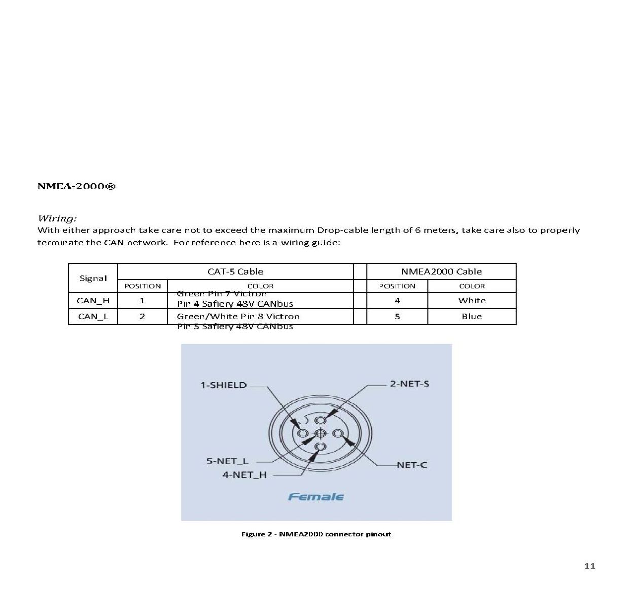
NMEA WIRED CONNECTION
Only the Vieo head unit and Connect 50 are linked by NMEA 2000.
One way is:
- Deploy an NMEA backbone
- Fit terminators either end (enclose end of line resistors)
- Install drop cables to Connect 50 and to Vieo
- Install the NMEA to Vieo Molex 4 Pin Connector
- Install the NMEA power injector to the backbone
An alternative way that reduces the protrusion fof the long NMEA connector rom the Connect 50 is:
- Deploy a NMEA backbone
- Fit a NMEA “T Piece” to the top of the Connect 50
- Fit a drop cable from the backbone to the “T Piece”
- Fit a terminator to the free end of the T Piece
- Fit a terminator to the free end of the Backbone
- Install drop cables to Connect 50 and to Vieo
- Install the NMEA to Vieo Molex 4 Pin Connector
RS485 CONNECTION
RS485 is galvanic isolated,
- Ch 30 = A and Ch 31 = B.
- LED indication 30 will indicate when transmitting message “Tx” and LED indication 31 will indicate when receiving message “Rx” to Connect-50.
- Two external 120-ohm terminal resistor must be installed in each end of the RS485-bus.
- Install the shield with only one end (suggest close to the Connect 50 grounded.
Line Resistance (Between CAN High and CAN Low) should read 60 ohms.
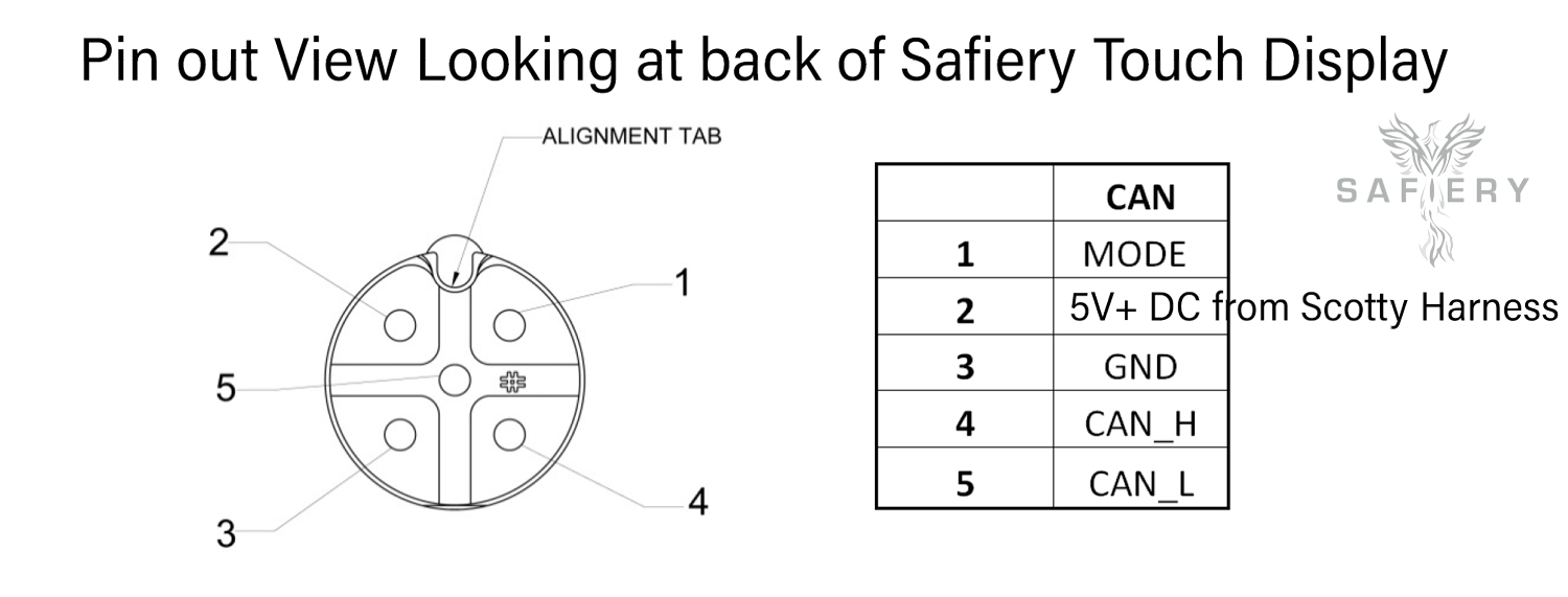
Scotty Touch Display CAN have 12V+ DC instead of 5V+ DC . This is only for 1500 or 3000 12-48 AND WONT WORK FOR 24-48.
So if the product suits, you can use 12V+ DC providing it is after the enable/power switch into Scotty harness so than when this is power cycled, the Touch Display is power cycled as well.