Installation wiring is split into two groups:
1. The Power cabling which has three components:
LS stands for Low side (which is the lower of the two connected voltages)
Negative or Ground which is common for both the Low Side and the High Side
HS stands for High side (which is the higher of the two connected voltages)
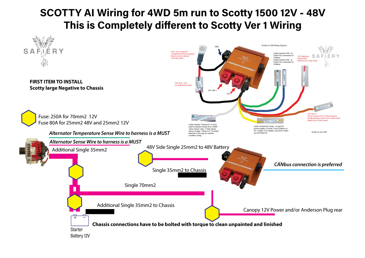
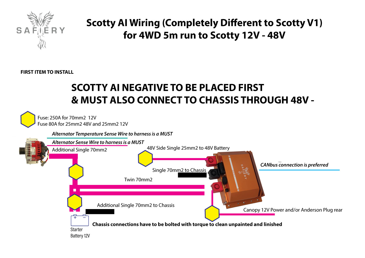
Protection against electrical/mechanical abuse:
Scotty AI has short circuit protection. However, a fuse protects the cable against electrical/ mechanical abuse. Each of the LS and HS cables need fuse protection. Because Scotty is bi-directional, both ends of each of the LS and HS cables need to be fused.
- The LS fuse must not be less than the maximum current capacity of the alternator.
- Look up tables which show the fuse size required to protect each cable.
A rule we use is the fuse should be less than the cable cross section in mm2 x 7.
As examples, a 70mm2 cable on the LS is protected by a 300A fuse or smaller and a 25mm2 cable on the HS is protected by a 100A fuse or smaller. If twin 70mm2 cables are used on the LS, each cable has to be fused independently and assumes to carry 100% of available current. These fuses may not be effective unless both the LS and HS share a common negative.
Best practice is to always install and check for a common negative first.
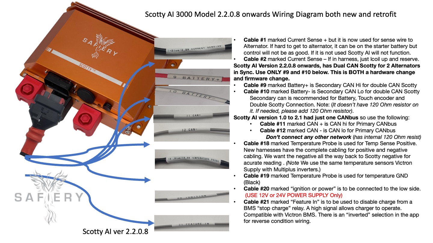
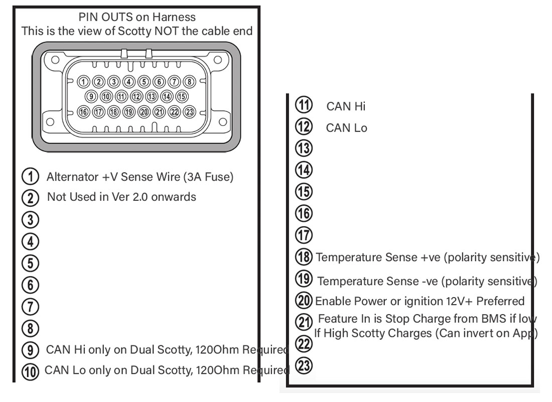
2. The “Control and Sense” cabling is captured in one of the “harnesses”.
- The alternator sense wire needs a small 3A fuse at the alternator. This sense wire is essential for Scotty AI to operate.
- The alternator temperature sensor is an accurate two wire sensor supplied separately. The red wire connects to the Temperature Sense + harness wire. The black wire connects to the battery negative close or at Scotty. This temperature sense wire is essential for Scotty AI to operate. Connect the temperature sense “lug” to the body of the alternator as close to the regulator end as possible.
- The ignition or enable wire is a LS powered wire for the microprocessor in Scotty AI. It should have a 3A fuse and have an breaker switch to turn off/ on.
- CAN Hi and CAN Lo connect to the HS battery Can BMS. A 120 Ohm precision resistor may be needed. Check the CAN wiring.
- The Function wire is reserved for future use.
- Ignore the yellow wire marked 5V for touch display. This is now 12v from an independent source.
.